- POWER WORLD SIMULATOR TRANSMISSION LINE FLOW GENERATOR
- POWER WORLD SIMULATOR TRANSMISSION LINE FLOW SOFTWARE
- POWER WORLD SIMULATOR TRANSMISSION LINE FLOW PC
It study about, a coupled heat, flow (CFD) and electromagnetic (EMAG) model of the permanent magnet brushless electric motor with electronic commutation was formulated and then validated
POWER WORLD SIMULATOR TRANSMISSION LINE FLOW PC
This information will be sent to the remote PC using Zigbee communication module. Microcontroller compares all these sensor data with respective set limits and accordingly the switches the relay. Various sensors employed in this design continuously monitors the parameters of the motor.
POWER WORLD SIMULATOR TRANSMISSION LINE FLOW SOFTWARE
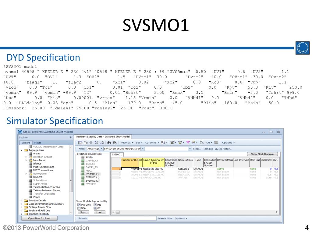
Perhaps the software you're using has two modes of operation, Power Flow and Transients or something like this.

It mostly depends on what kind of simulation you would like to perform. 0.2+j0.5 Ohm/km, so you calculate line reactance as 0.5 Ohm/km multiplied by line length, as well as resistance and also capacitance given as y = 3.3e-6 S/km, so multiply by line length. The values of "Internal Sequence Impedances" are: negative - use x2, zero - use x0, and perhaps x" could be positive seq., however it should be x1 which is xd and it's usually about 200-250% of the generator's base reactance that you'd calculate from U^2/S (probably you need to convert them to pu's as default value is 1, so type just what you have on your picture).įor the line sequence impedances they are given on your picture as eg. (Maybe "power swings" text is only to tell that the busbar is not a reference node). Typically the xd' is about 1.5-2 greater than xd", for 100-200 MVA generators xd" = 0.25, (for smaller units it can be 12%), xd' = 0.4, so obviously data given is not xd'. However, if you're going to calculate power flows, this value is not necessary and can be omitted (so why then is it given on your picture?).īecause the text on the picture says something about "power swings", perhaps you are to simulate swings, so no xd" should be used but xd' rather.

POWER WORLD SIMULATOR TRANSMISSION LINE FLOW GENERATOR
The other idea is that you inserted a generator-transformer unit while you should insert a generator only. This value is required if you're going to simulate short-circuits, so maybe it is allowed to insert in other tab (it should be in "Fault"). Read this file for more information about PowerWorld.Īs Andy aka wrote, there is x" (xd") which is sub-transient reactance in d-axis of the generator and it is the basis machine parameter and should be allowed to enter (I can't believe it is not).

The voltages in all buses should be around 1-pu. I already simulate your system, and I think it is easy. What is your tap ratio in the transformers side? Remember, the typical value for the tap-ratio is between 0.9 and 1.1. This is just for the first line, you can do the same for the other.Īlso, you can enter the positive impedance in the "Parameter" window, and the zero impedance can be entered separately in the "Fault Info" window. The positive/zero sequence impedance can be found by dividing the given values by the the \$ Z_ \$, and then multiply it with the line length: Also, you already have the line lengths in km. Look at the following image:įor the second part, you are wrong! Why did you put the data in Ohm/km? You should put it in per unit. You can enter these data in the "Fault" window of the "Generator Information for Current Case". \$ x^"\$ is the internal positive reactance.\$x_2\$ is the internal negative reactance.Maybe this will help you:įirst, the generator ratings are given as: I will try to answer all of your questions.


 0 kommentar(er)
